How does it work?
An engineering and technical icon
Tvindkraft continues to inspire people both in a technical and artistic capacity.
Tvindkraft has also been recognised internationally and was awarded the European Solar Prize in 2008 for the educational effect the turbine has had on the local community.
The Tvindkraft turbine has also helped to create a strong engineering legacy for the technical community of Denmark.


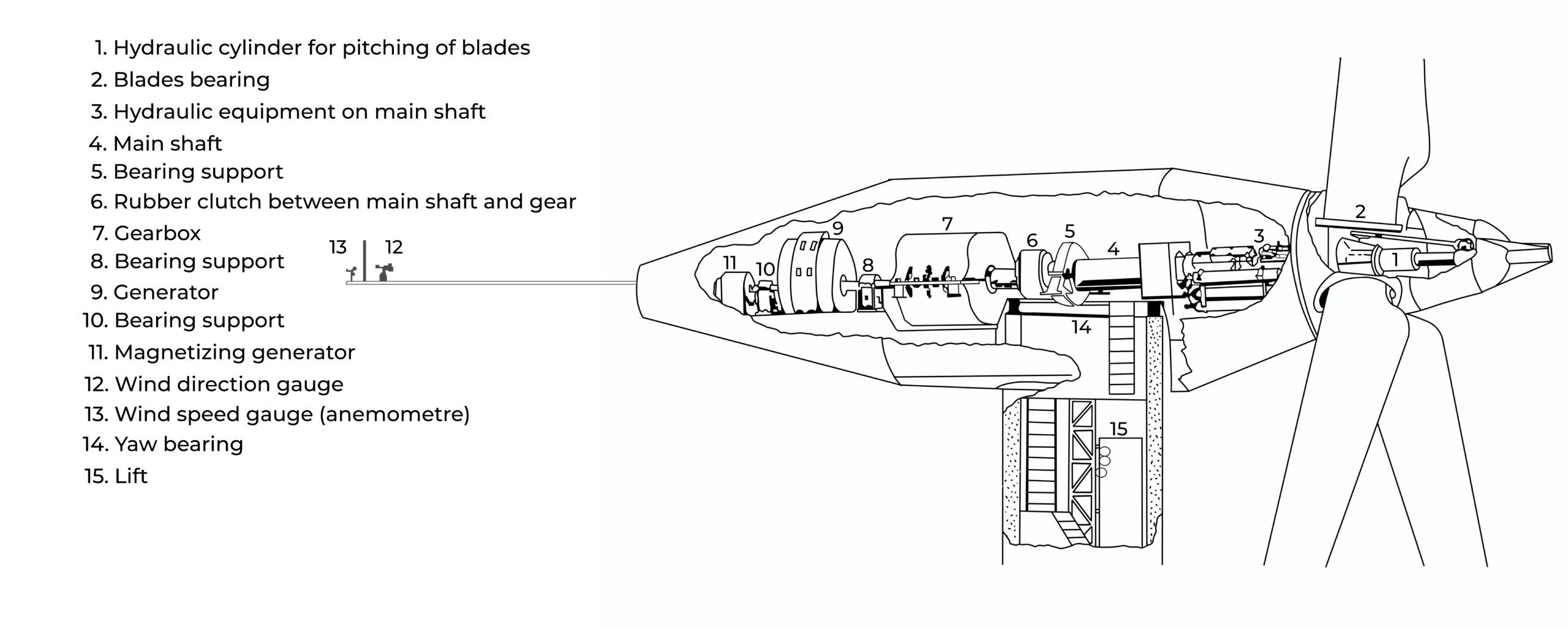
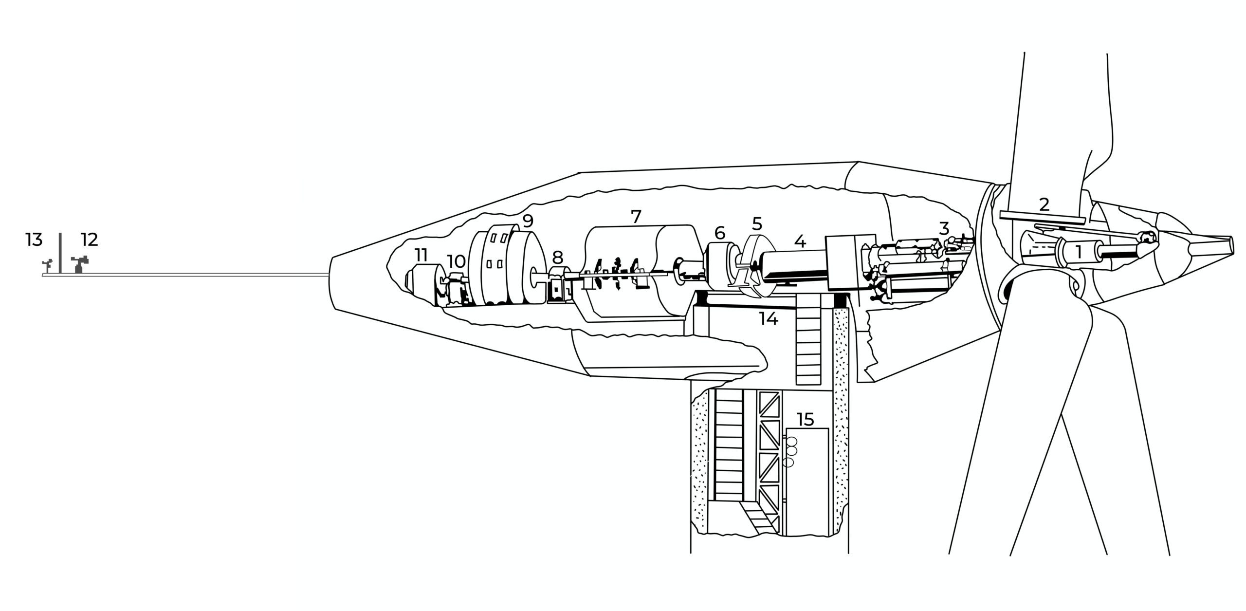
The individual parts inside the nacelle
-
- We start in the rotating hub to which the blades are fastened. Here, we see in the middle the white main cylinder which pitches the blades into the wind.You are not allowed to move about in the hub if the pitch mechanism can be activated. At regular inspections we check gauges, hoses, wires and bolts in the hub.
- In the upper part of the hub we see one blade bearing to which the blade is attached. To the blade bearing is attached a pulling rod which pitches the blade as the main cylinder moves in and out.
- At the very front inside the nacelle we find the various blade hydraulic systems, mounted on the main shaft. There is one system for regular operations and several for emergency stops The hub is attached to the main shaft which goes into and through the nacelle.
- The main shaft goes from the hub all the way to the gear box. It comes from a ship’s graveyard in Rotterdam. It used to serve as a propeller shaft in an oil tanker.
- In front of the hydraulic systems is the big main bearing in which the shaft rotates (not visible in the drawing). At the other end is the small main bearing. Both are roller bearings.
- Behind the small bearing there is a rubber clutch which will protect the gear and the generator in the event of a breakdown. On it is placed a circle of teeth, counting how fast the windmill is running.
- The big box is the gear. It is bigger than a Volkswagen Beetle and weighs some 20 tons. It used to be a spare gear at a Swedish copper mine. It has a fixed exchange of 1-20, making the shaft run fast enough to drive the generator.
- After the gear comes the bearing support for the generator (Also 10).
- The generator is a synchronous AC generator. It was used in a Swedish paper mill and weighs about 12 tons.
- Second bearing support for generator.
- This is the magnetising generator. It supplies power to the rotor of the main generator in order to magnetise it.
- At the back of the nacelle we find the wind rod. It is 6 meters long. On it are the wind gauge and the wind vane.
- The wind gauge (anemometre) tells the blades to pitch off as the wind increases. The wind vane tells the yawing system to turn the hat so the blades are always placed in the wind. The vertical stick is a lightening rod.
- This is the yawing bearing on which the whole hat rotates in order to always stay in the right wind direction. This is controlled by the wind vane. The mechanism that turns the hat is two hydraulic cylinders that move two arms in and out of the big cogwheel, thus turning the hat around tooth by tooth.
- We get up and down the tower with the original construction lift, which has been modified to fit inside the tower.
